|
stuffware.co.uk
|
Japanese VBI
Introduction
I've spent a while investigating the use of VBI technology in Japan. One slight difficulty here is that this technology doesn't appear to have a consist name (unlike, say Teletext) - a few names by which it might be referred to:
The Japanese word 文字 (moji) literally means "character" - as in a character in a particular script or font. In this context it could probably also be interpreted as "text". 字幕 (jimaku) is the Japanese word for subtitles or captions. Finally 放送 (hoso) means broadcast.
The tranmission and multiplexing mechanism is defined in ARIB STD-B5 (ARIB website).
Please Note: this is very much a work in progress - there is no software to download yet, and maybe there never will be!
I'm just trying to document as much of this progress as possible in the hope it might prove useful to something else.
Motivation
Yes I'm aware that anything analogue/VBI based is a technology with a limited lifespan - the switch over to digital television in Japan will eventually make it completely redundant. However Japan has decided to go with an entirely encrypted system for their digital broadcast standards, which means there will be no scope for independent developers (like me) to write novel and interesting applications. Currently (summer 2006) whilst regular digital TV receivers are widely available, there are no retail available devices which can be connected to a PC (USB, PCI, PCMCIA, whatever). Even when (if?) these become available, all the data is going to be encrypted, and the only software that will be available to work with them will be written by large companies who have been approved by the relevant standards bodies.
For someone who isn't a native Japanese speaker, television here is obviously not a very accessible medium. North America and Europe benefit from widely available closed captions / subtitles in broadcast content. It turns out that the largest users of these services are not in fact the hard of hearing, but those people who have English (or whatever the principal language is in the country in question) as a second language. Particularly with English, many people experience that it can be significantly easier to read than to listen to, and often the combination of the two can tip the balance between a meaningless and meaningful television experience.
Whilst most people learning Japanese as a second language may not find reading significantly easier than listening (particularly those coming from countries which use the Latin alphabet), I think it could still be a significant help. I know I'd find Japanese captions useful.
So, captions are of course available in Japan right now, simply by going out and buying a digital TV. Well, the expense of that aside, the problem is you've then got an entirely closed system. What I really want to be able to do is write my own software to display these captions, so I can add in a number of features which will make it easier to read for somebody like me who is learning Japanese. There is basically no chance at any point in the near future that an independent developer like me would be able to write their own software for receiving ISDB (the Japanese digital TV standard).
With your own home grown Japanese captions decoder there are a number of interesting features you could add which would be really helpful to people learning Japanese:
How do we know it is there in the first place?
A friend of mine here in Japan managed to get hold of a kind of set top box made by a Toshiba, which I think is the TT-X3 (another similar model is the TT MT4). This is described on their website as a ITビジョン・モジネットチューナー (IT vision - mojinet tuner). It looks like the TT-X3 has gone out of production, but the TT-MT4 may still be available - although I wouldn't have a clue where you'd go to find one.Getting at the VBI
The first hurdle to overcome was to get at the VBI data in the first place. Luckily it seems Microsoft require full VBI access for their certification program (see here), which means most recent TV tuner device which work with Windows drivers have a good chance of letting you get at the VBI signal.
Identifying ARIB STD-B5 VBI Data
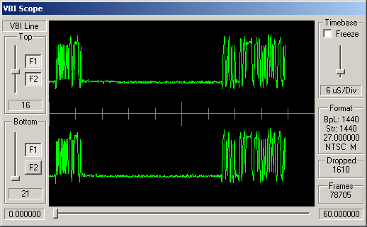
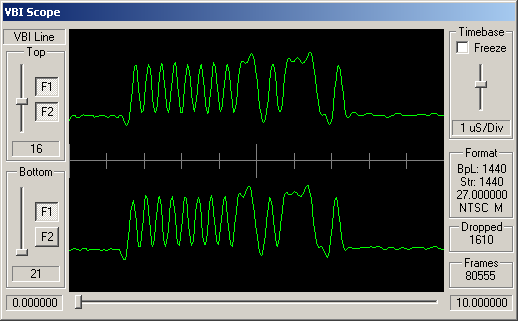
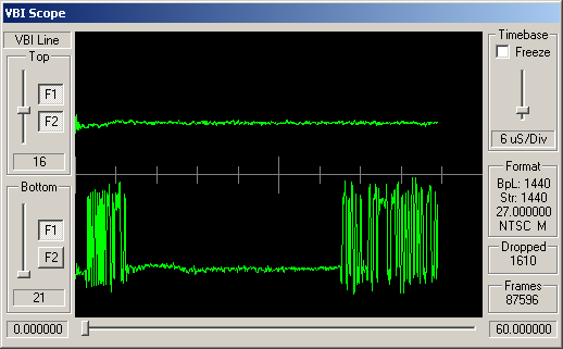
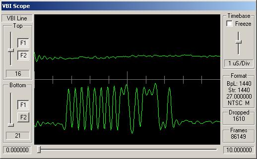
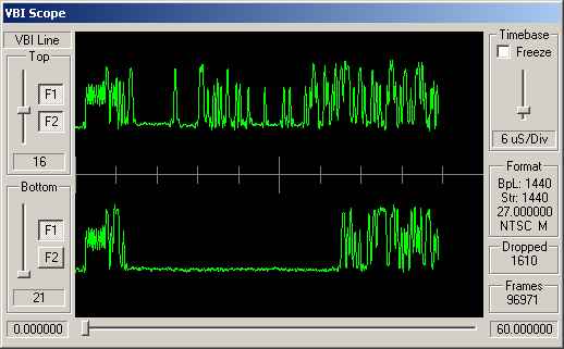
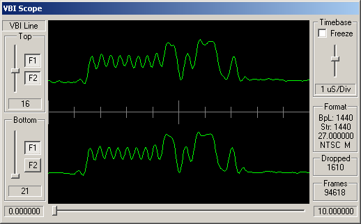
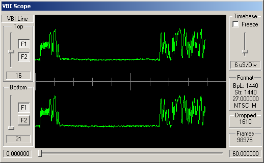
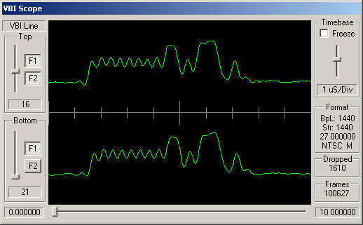
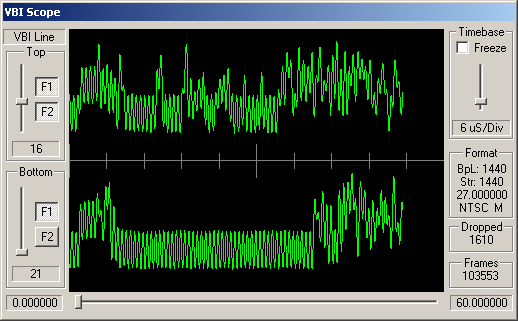
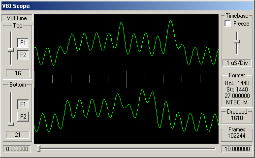
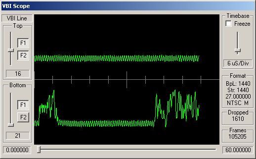
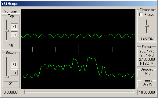
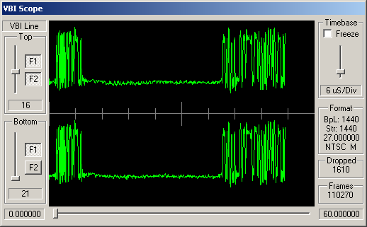
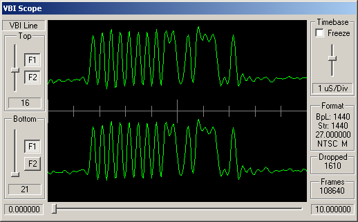
How can you tell which VBI data is adhering to STD-B5? Well, like many similar VBI standards, the STD-B5 defines that the data should begin with a clock synchronisation signal (sometimes referred to as a runin). This represents 16 bits of data, and should be a smooth oscillation between ones and zeroes - '1010101010101010'. So somewhere near the start of the VBI line you'd hope to see a clean sine wave with 8 peaks and 8 troughs.
Following this bit synchronisation, you should see a byte synchronisation signal - for STD-B5 data this is the bit string '11100101'. So you'd expect to see high values over the space occupies by three bits, then low values for two bits, then high, low, high.
For the channels, above, simple visual inspection suggests that the following carry data conforming to the ARIB STD-B5:
Cable channels 8, 21 and 26; and antenna channels 5 and 7.
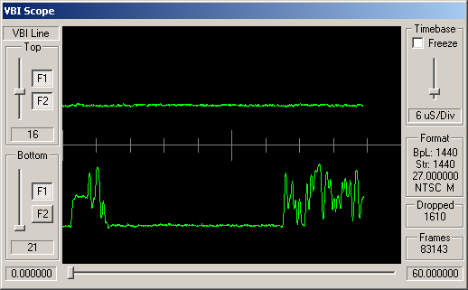
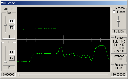
The remaining channels do appear to have some kind of digital signal modulated into these VBI lines, but this doesn't look like STD-B5 data.
A brief aside about other VBI standards
There are a number of VBI based data transmission standards in use throughout the world. One of the major ways in which they vary is in the number of bits conveyed per VBI line.
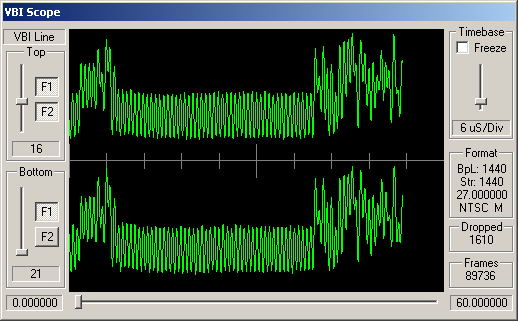
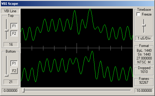
Turning the Waveform into a Bitstream
Hopefully the above VBI waveform images give an idea of the format the incoming data is in. Typically a VBI line is received as 1440 luminance samples, with one byte per sample. From this we need to retrieve 296 bits. Broadly speaking, as the scheme used is basically amplitude modulation (sometimes referred to as NRZ - Non-Return to Zero), '1' bits will be represented by a high luminance values, and '0' bits as low luminance values. The difficult bit is working out the following three values:
The current approach I've adopted to work out these values is based on fixing points for the runin. Roughly speaking I do the following:
Decoding the bitstream
The 296 bits conveyed in the VBI line are divided up as follows:
The error correction scheme used here appears to have been developed specially for Japanese VBI data. It is a (272,190) "difference set cyclic" scheme. The first 24 bits (bit/byte synchronisation) are constant values so are not included in the error correction. Effectively then we have 190 bits of data, and 82 bits of checking - thus it is described as (272,190).
This kind of coding theory is way beyond me, but thankfully it may not be necessary to fully understand the underlying maths in order to make use of it, as there is a great piece of open code available on the web which implements this algorithm. See here - Mojinet Internet Gateway - this page, in Japanese, describes a project to read Mojinet data from an incoming VBI signal and make it available over TCP/IP. This has a very important contribution in that it includes a C implementation for handling the (272,190) error correction scheme.
|
stuffware.co.uk
|